Home Industry Telecom A Practical Guide to Fiber Opt...
Telecom
CIO Bulletin
09 April, 2026
Fiber optic networks are the foundation of modern connectivity. They carry everything from streaming video and cloud data to critical communications for hospitals and emergency services. But building, maintaining, and troubleshooting these networks requires a carefully assembled toolkit of specialized instruments and devices, each designed to handle a specific stage of the installation or maintenance process. Understanding what each piece of equipment does and when to use it is essential for anyone working in or around fiber infrastructure.
The range of fiber optic equipment available today covers every phase of a network's lifecycle, with each tool serving a distinct purpose. Technicians working on telecommunications buildouts, data center interconnects, or industrial sensing systems rely on these tools daily. Choosing the right instrument for the job directly impacts splice quality, network uptime, and long-term reliability. With fiber deployments accelerating across sectors, a practical understanding of this equipment has never been more valuable.
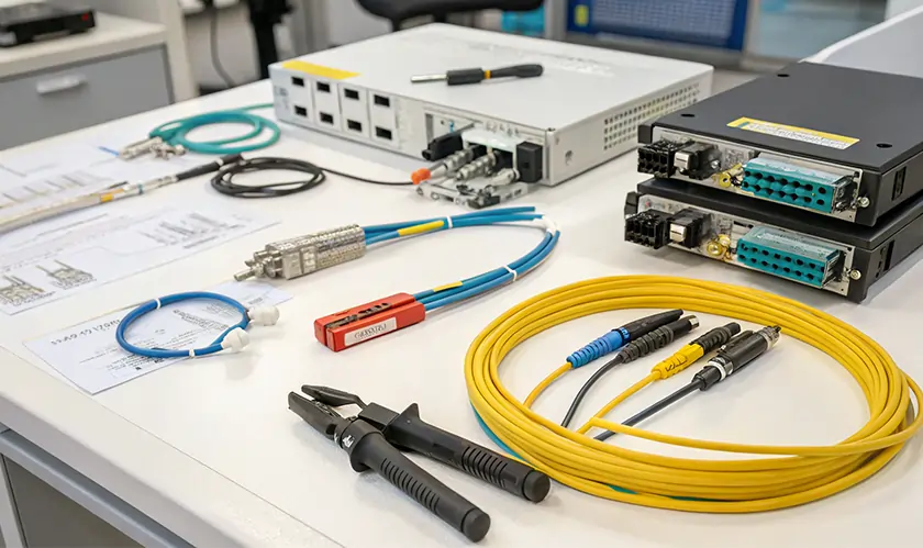
Every fiber optic job begins with cable preparation. Before any splicing or termination can happen, the fiber must be properly stripped, cleaned, and cleaved. Cable jacket strippers remove the outer sheath without damaging the delicate fibers inside. Buffer tube strippers then remove the tight or loose buffer coating surrounding individual fiber strands. Precision fiber cleavers score and break the bare glass to produce a flat, mirror-smooth end face.
A clean cleave is critical because even a slight angle or chip at the fiber tip can cause significant signal loss at the splice point. Lint-free wipes and high-purity isopropyl alcohol round out the preparation stage, keeping the bare fiber free from oils, dust, and other contaminants.
Fusion splicers are among the most important tools in any fiber technician's inventory. These machines align two prepared fiber ends and use an electric arc to melt and permanently fuse them together. The result is a continuous glass path with extremely low signal loss, often below 0.05 dB for single-mode fibers.
There are two primary types. Cladding alignment splicers position fibers based on the outer glass surface and are suitable for multimode work or less demanding applications. Core alignment splicers use advanced imaging to detect and align the actual light-carrying cores, delivering the highest precision for single-mode and long-haul networks.
Specialty models go further still, handling non-standard fibers like polarization-maintaining, large-diameter, and rare-earth-doped fibers used in laser systems, medical devices, and defense applications.
Optical power meters measure the strength of light signals passing through a fiber. Paired with a calibrated light source at the opposite end, they form an optical loss test set (OLTS), the standard tool for verifying that a fiber link meets performance specifications.
According to the Fiber Optic Association, optical power measurement is the most fundamental parameter in fiber optic testing and is required for nearly every test scenario. Technicians use this combination to measure insertion loss across installed links, confirming that connectors, splices, and cable runs fall within acceptable limits before a network goes live.
A visual fault locator (VFL) is a simple but effective troubleshooting tool. It injects a bright visible laser, typically red, into one end of a fiber. The light travels through the strand and becomes visible at points of damage, tight bends, or poor connections, making it easy to trace fibers and pinpoint problem areas.
VFLs are particularly useful during installation for quickly verifying continuity and identifying fibers in dense cable bundles. They are inexpensive, compact, and require no complex setup, which makes them a staple in nearly every fiber technician's toolkit.
The optical time domain reflectometer, or OTDR, is the most comprehensive diagnostic tool available for fiber networks. It sends a pulse of light down the fiber and analyzes the signal that scatters back, creating a detailed trace that shows the location and magnitude of every event along the link. Splices, connectors, bends, and breaks each produce a distinct signature on the trace.
OTDRs are essential for characterizing new installations, verifying splice quality, and troubleshooting faults in existing networks. Their ability to test a fiber link from one end, without requiring access to the far end, makes them indispensable for outside plant work and long-distance routes.
No single piece of equipment builds or maintains a fiber network on its own. Each tool addresses a specific need, from preparing and joining fibers to testing, inspecting, and troubleshooting completed links. The best results come from using the right instrument at the right stage of the process and maintaining all equipment according to manufacturer specifications. As fiber networks continue to expand into new industries and applications, familiarity with this essential toolkit is becoming a core skill for technicians, engineers, and project managers alike.


.webp)

.webp)


 consultants ltd.jpg)


